

Page 54 [54]

OCR
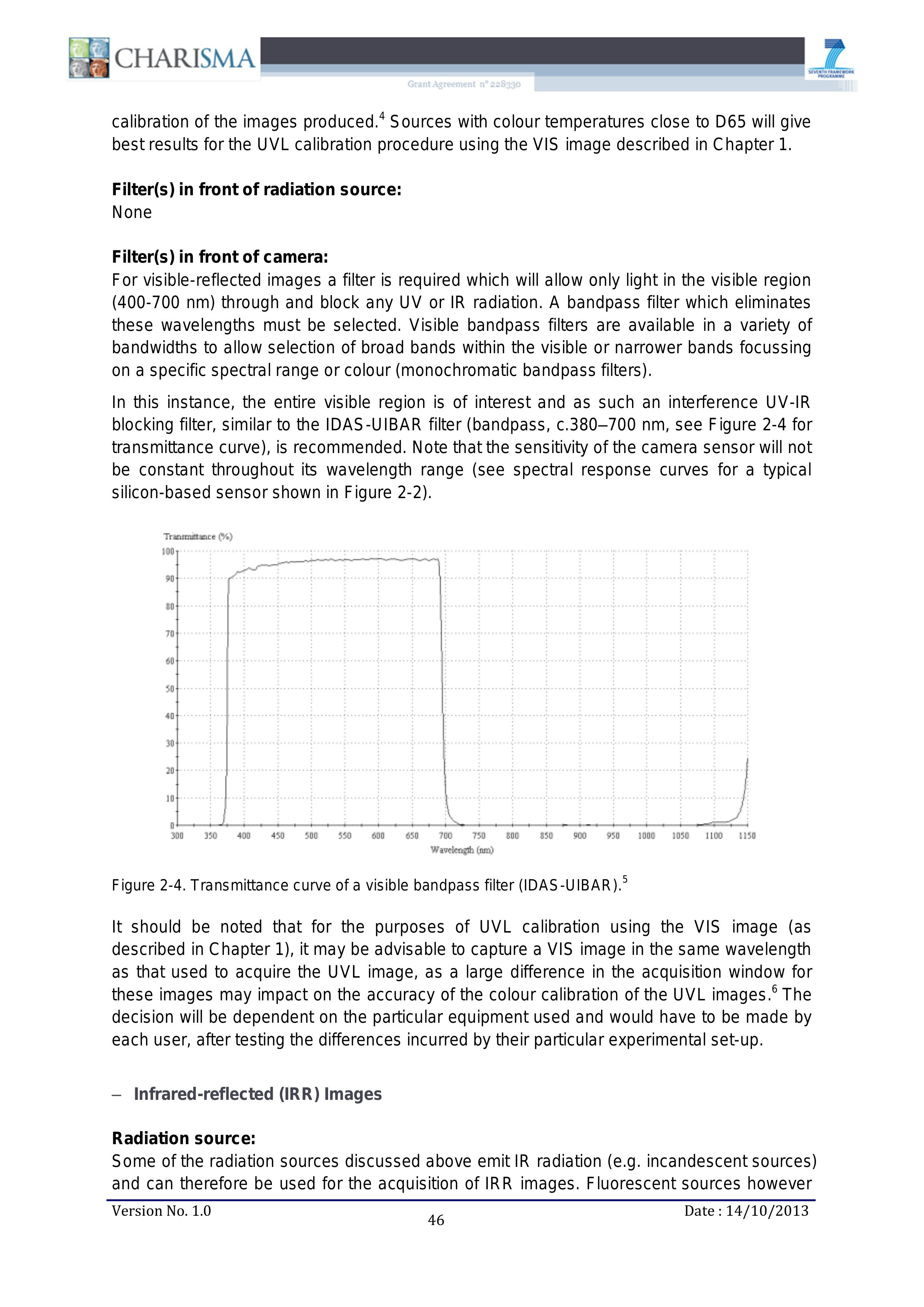
calibration of the images produced.! Sources with colour temperatures close to D65 will give best results for the UVL calibration procedure using the VIS image described in Chapter 1. Filter(s) in front of radiation source: None Filter(s) in front of camera: For visible-reflected images a filter is required which will allow only light in the visible region (400-700 nm) through and block any UV or IR radiation. A bandpass filter which eliminates these wavelengths must be selected. Visible bandpass filters are available in a variety of bandwidths to allow selection of broad bands within the visible or narrower bands focussing on a specific spectral range or colour (monochromatic bandpass filters). In this instance, the entire visible region is of interest and as such an interference UV-IR blocking filter, similar to the IDAS-UIBAR filter (bandpass, c.380-—700 nm, see Figure 2-4 for transmittance curve), is recommended. Note that the sensitivity of the camera sensor will not be constant throughout its wavelength range (see spectral response curves for a typical silicon-based sensor shown in Figure 2-2). Transrruttance (%c) 1100 1150 Wavelength (nm) Figure 2-4. Transmittance curve of a visible bandpass filter (IDAS-UIBAR).° It should be noted that for the purposes of UVL calibration using the VIS image (as described in Chapter 1), it may be advisable to capture a VIS image in the same wavelength as that used to acquire the UVL image, as a large difference in the acquisition window for these images may impact on the accuracy of the colour calibration of the UVL images." The decision will be dependent on the particular equipment used and would have to be made by each user, after testing the differences incurred by their particular experimental set-up. — Infrared-reflected (IRR) Images Radiation source: Some of the radiation sources discussed above emit IR radiation (e.g. incandescent sources) and can therefore be used for the acquisition of IRR images. Fluorescent sources however Version No. 1.0 46 Date : 14/10/2013 kanal